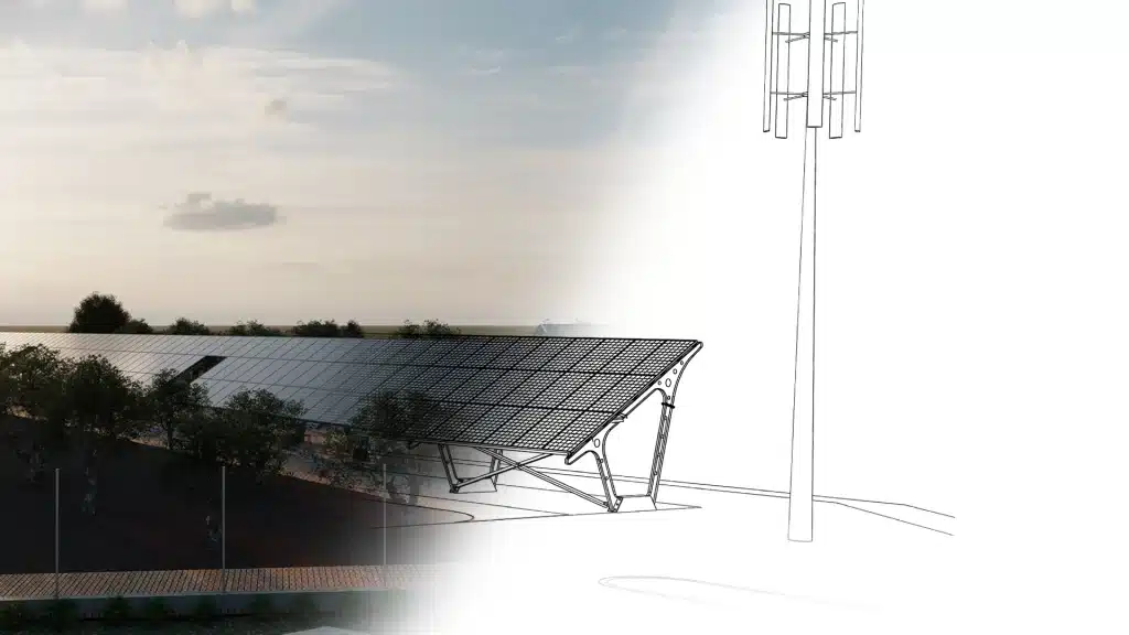
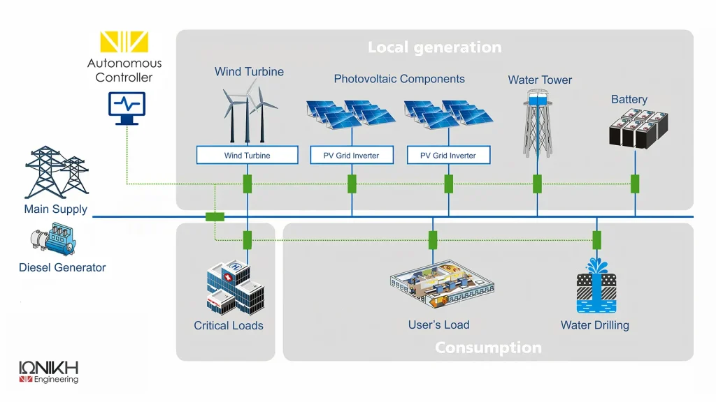
As the installation of Renewable Energy Sources (RES) expands, a critical need arises for the best possible utilization of the produced energy. The answer to how to achieve the production and optimal management of renewable energy lies in these lines. The proposed system includes photovoltaic panels and Vertical Axis Wind Turbines (VAWTs), which produce energy based on sunlight and wind speed. The surplus energy can either be stored in available batteries or converted into potential energy through pumped hydro, lifting water from a lower reservoir to a water tower. This energy can be utilized for electricity generation when demand exceeds production. Regarding the water in the water tower, the conversion of potential energy back into electricity is done via a hydro-generator. In cases where production, combined with energy availability, cannot meet demand, a connection to the HEDNO network has been planned, and for cases of extensive outages in the provider's operation, the installation of a diesel generator has been anticipated.
The standard microgrid has the innovation of centralizing and features the DC Bus as its main energy source. This means that by utilizing the DC Bus, the producer can connect various networks, which can operate independently and/or in parallel. To clarify, three-phase inverters can be connected to drive three-phase loads, while two independent single-phase inverters can be connected to drive two independent single-phase loads. The controller, having predefined the critical loads, can perform calculations for all networks, "thinking" and "deciding" for all at once as if it were a cohesive network.
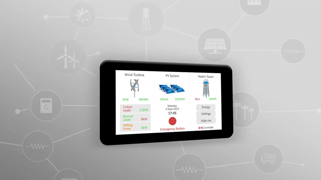
Naturally, the organization and prioritization of all the aforementioned capabilities of the system is the responsibility of a pioneering autonomous controller (AmEFC), which makes decisions regarding energy utilization. A key factor influencing energy distribution is the categorization of loads. Depending on the criticality of the loads, their priority is determined. The other factor that influences the controller’s decisions is the forecasts it receives regarding sunlight and wind speed for the upcoming days. Furthermore, through this innovative software, access to operational data from all system components is provided, allowing for parameter modifications and reduction of wear and tear on the microgrid.
An overwhelming advantage of the system as a whole is the potential for expansion of each of its segments. Particularly noteworthy is the innovation in the selection of inverters, which is precisely related to the project's objective. This very capability is what paves the way for the implementation of the proposal on a larger scale. The aim is to interconnect such microgrids within the urban fabric and to enhance energy management even further through the collaboration of respective controllers.
Goals
The main objectives on which this study is based as a whole are the following:
- Reliability and durability through dynamic adjustments to electricity production and consumption.
- Optimal energy management with balancing supply and demand through assessment of capacity of energy production and knowledge of weather forecasts.
- Scalability, which is achieved through the ability to adapt the systems to changes in demand, but also the flexibility to integrate new RES. Also particularly important is the possibility of microgrids to operate on a city scale, exchanging resources with other microgrids.
Detailed presentation of microgrid sections
Subsequently, a more detailed presentation will be given regarding the design, theoretical framework, technological advancements, and practical applications of each segment of the microgrid, shedding light on their potential to prevail in the field of renewable energy source integration
1. Basic elements of the microgrid standard
- Solar Photovoltaic (PV) Systems: Based on modularity, they allow the system's scalability and adaptation to changing energy needs
- Vertical AxisWind Turbines (VAWT) Their design ensures low acoustic disturbances, while ground-level accessibility simplifies maintenance tasks. Additionally, these wind turbines demonstrate increased efficiency even under adverse weather conditions, harnessing energy even when conventional wind turbines may face challenges. The design here is also envisioned to be modular, facilitating future expansions as needed.
- Pumps Utilizing the ability of the gravitational potential energy, the pumps offer a reliable and επεκτασιμό medium for storing energy for future use.
2. MPPT charge controllers
Another integral part of the microgrid are the MPPTs, whose role is to track the maximum power point of Renewable Energy Sources (RES). Designed to optimize the utilization of exported energy, each RES is individually connected to its corresponding MPPT.
Also facilitate the exchange of data in real-time through direct configuration of the data in the cloud. The interconnection of these MPPTs is completed in the DC Bus, which operates as a single centre for the distribution and management of energy. The modular approach ensures the scalability.
3. Battery arrays
To enhance the reliability of the microgrid system, battery arrays have been integrated into it. The microgrid offers flexibility in battery technology selection, providing options for either Lead-Acid batteries or advanced Lithium-ion battery systems.
Each battery array is equipped with a state-of-the-art Battery Management System (BMS), which plays a vital role in safeguarding the health and lifespan of the batteries through precise control of their charging and discharging processes.
Just like the MPPTs, Battery Management Systems (BMS) also have the capability to transmit real-time data regarding battery performance and health metrics to the battery manufacturer's cloud platform. This integration of data paves the way for remote monitoring, health diagnosis, and predictive analysis, providing stakeholders with valuable information about battery performance and expected lifespan.
4. Single-phase inverters
If energy consumption requirements expand in the future, the architecture of the microgrid easily allows for scalability without necessitating a complete overhaul of the central infrastructure.
These inverters are not merely passive elements. They are equipped with sensors and communication units that continuously monitor the flow of energy. These data are transformed in real-time into the cloud platform maintained by the inverter manufacturer. The integration with the cloud facilitates remote monitoring, analytical processing, and predictive maintenance, reducing inertia and ensuring continuous energy delivery.
Additionally, the inverters are interconnected, forming an internal communication network. This interconnection among the inverters is crucial for coordinating their operations, maintaining phase consistency, and ensuring a balanced load distribution in the three-phase system.
5. Microgrid loads
Within the complex architecture of the AmEFC microgrid prototype, energy consumption evolves intelligently based on the significance and priority of the connected loads. The following load categories are identified in our system:
Critical Loads: Typically included in these are life support systems, regulated healthcare environments, emergency lighting installations, communication systems, and other essential services. The system operates on the premise that critical loads will never cease their function. | Normal Loads Representing the majority of consumption, they encompass the devices and systems of daily life, from lighting and climate control to household appliances. Although these loads also benefit from uninterrupted electrical power supply, there exists a hierarchy of service. | Hydro Tower Load In cases where energy production significantly exceeds consumption, instead of letting this energy go to waste, the system directs it to the hydro tower. These pumps, after evaluating weather conditions and battery data, convert the surplus electrical energy into potential energy. |
6. Support from HEDNO and auxiliary sources
Network Connectivity: It provides support, especially during extended periods of low renewable energy production or during unforeseen spikes in demand. The system, which draws energy from the grid, ensures that its internal energy balance remains unaffected, while in case of energy surplus, it can be fed back into the grid
Diesel GeneratorThis compensatory energy source can be activated immediately by bridging any gaps in energy, ensuring that the microgrid remains operational and continues to power its loads without interruptions.
7. Grid discharge capabilities
Another critical point is the management of excess production. In systems that include wind turbines, it is very common to exceed the production, not only the demand, but also the capacity of the battery, especially if the associated units battery is saturated. In contrast with the conventional methods of dealing with the excessive supply, such as the disconnection of the wind turbine or the redirection of energy in a resistor, the standard microgrid AmEFC presents an innovative solution. In the case of the water tower, in which is stored the water, reaches the maximum, it has provided a backup plan to redirect the overflow into an adjacent creek. This ensures a constant balance and prevent the waste of energy.
8. AmEFC Software: The processing center of the microgrid
The efficiency of the AmEFC microgrid is not only found in its technical characteristics. At the heart is AmEFC software, an advanced computing and control tool designed to seamlessly harmonize the complex combination of energy flows throughout the system. The main functions of this software are the following:
Equipment Data Flow to the Cloud: Almost every device in the microgrid, not only performs its designated function, but constantly communicates important real-time operation data to the corresponding clouds, thus increasing system performance.
Data Aggregation and Storage: All information is systematically organized and stored, which ensures that every decision the system makes is based on complete, up-to-date information.
Advanced Computational Strategies: Using Optimal Power Flow (OPF) strategies, it determines the most efficient distribution of power in the network, ensuring that each element operates at the peak of its potential while meeting the demands of the connected loads.
Reinforcement Learning (RL)-control: The software learns from historical data, recognizes patterns and adapts to new situations and in this way RL makes its predictive decisions.
Real-time decision-making and automatic control: The combined use of OPF and RL ensures that the software is also proactive. The system continuously makes real-time decisions to maintain optimal energy flow and system efficiency.
9. The backbone of AmEFC execution
The collaboration between software and hardware ensures seamless power flow, ensuring optimal system performance and reliability. More specifically:
Hardware Interface: At the core of the AmEFC controller's functionality is its comprehensive electrical connectivity to a large number of microgrid devices and loads. This is achieved via a relay panel. These relays operate with or without an interface, allowing the controller to organize power distribution by making or breaking connections whenever required.
Client-side software functionsTailored specifically for the specific microgrid requirements, this software continuously retrieves data from the Cloud Center, leveraging it to make timely decisions about power allocation and flow.
Dynamic Power Flow Control: The software can quickly connect or disconnect various components, allowing it to respond immediately to changing energy demands or fluctuations in supply.
10. Challenges of interconnection and opportunities for AmEFC microgrids in urban scaling.
A fundamental challenge lies in synchronizing multiple microgrids with various production capacities, consumption patterns, and operational conditions. The constant expansion of Renewable Energy Sources (RES), which heavily depend on environmental factors, means that in scaling up these microgrids, there can easily be microgrids producing surplus energy while others fall short at that moment
Read more about Autonomous controller microgrid
Results and conclusions
A pivotal point of understanding before analyzing the system's performance is the initialization stage, characterized by zero energy or storage production. This stage serves as the reference point against which we'll assess the system's response to various external environmental influences. The adaptability and efficiency of the AmEFC can be better observed when the system is subjected to a series of weather conditions. To differentiate this, we classify climatic conditions based on two primary factors: solar radiation and wind speed. These factors are further divided into three discrete categories for detailed analysis.
The differentiation of the categories is based on
Solar Radiation
- Day with high sunshine
- Day with moderate sunshine
- Day with little sunshine
Wind Speed
- Day with high wind speed
- Day with moderate wind speed
- Day with low wind speed
The following sections will examine the detailed interaction between these climatic conditions and the corresponding energy production, revealing the resilience and reliability of the AmEFC microgrid system.
Sunshine (w/m2 high) | Wind (m/2 high) | Moderately sunny (w/m2 ) | Moderately windy(m/2 ) | A little sunny(w/m2 ) | A bit windy (m/2 ) |
---|---|---|---|---|---|
0 | 4.1 | 0 | 3.8 | 0 | 0.3 |
0 | 5.2 | 0 | 4.0 | 0 | 0.4 |
0 | 6.5 | 0 | 4.3 | 0 | 0.5 |
0 | 7.3 | 0 | 4.5 | 0 | 0.7 |
100 | 8.0 | 10 | 4.7 | 10 | 0.8 |
400 | 8.5 | 50 | 5.0 | 30 | 0.9 |
600 | 9.0 | 150 | 4.8 | 50 | 1.0 |
800 | 9.3 | 300 | 4.6 | 70 | 1.1 |
900 | 9.5 | 400 | 4.5 | 90 | 1.2 |
1000 | 9.8 | 450 | 4.7 | 100 | 1.3 |
1100 | 9.4 | 350 | 5.1 | 110 | 1.0 |
1000 | 8.7 | 300 | 4.9 | 120 | 0.8 |
1100 | 7.8 | 450 | 4.6 | 130 | 0.6 |
1000 | 7.2 | 500 | 4.4 | 120 | 0.5 |
900 | 6.6 | 450 | 4.2 | 110 | 0.4 |
Weekly simulation of the AmEFC microgrid
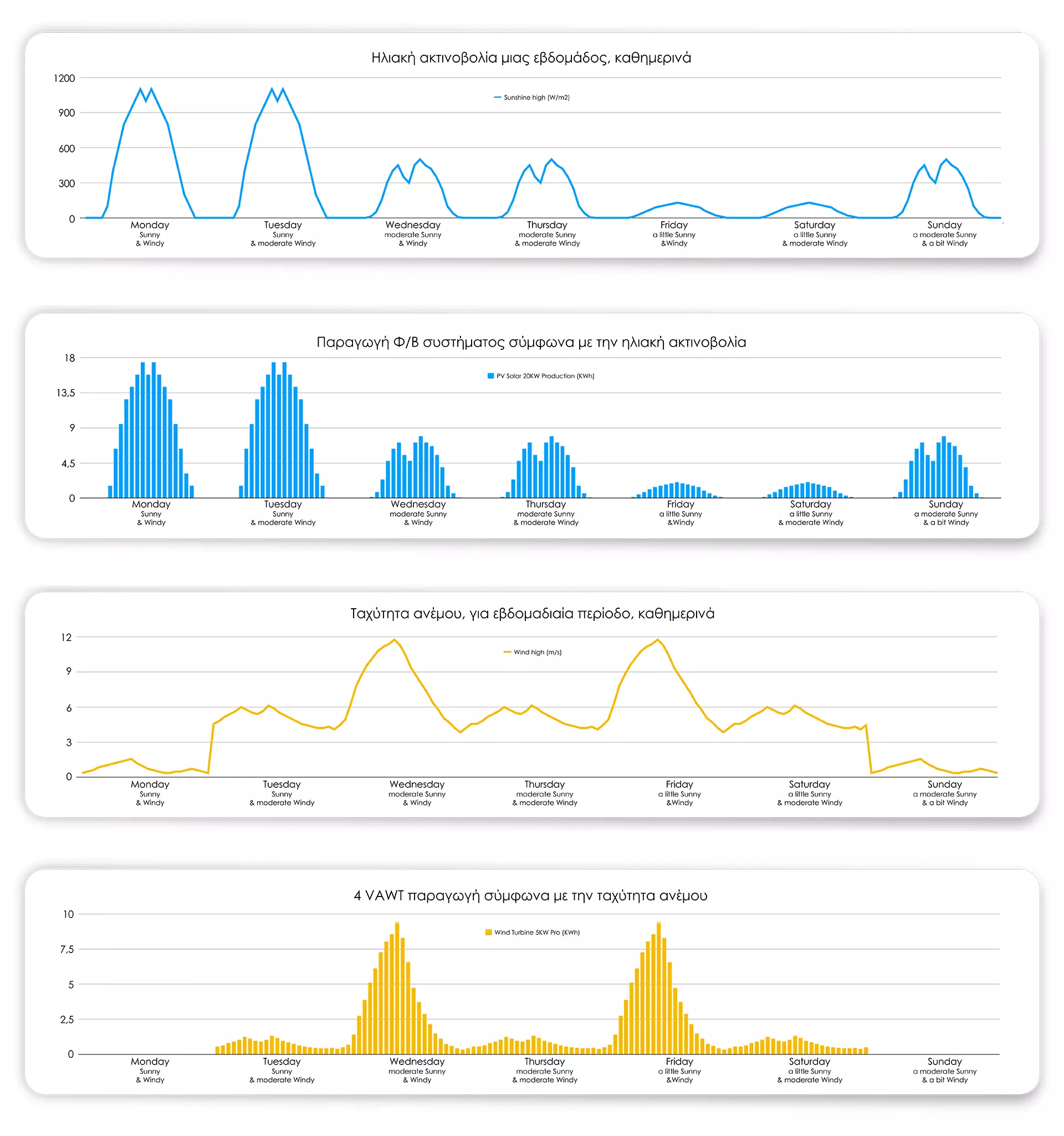
To rigorously test the AmEFC microdistribution system and, more importantly, the controller's operational performance, a full week-long simulation was set up. The simulation was structured to cover a variety of climate conditions by combining the aforementioned categories of solar radiation and wind speed. The sequence provides a comprehensive picture, covering both optimal and worst-case conditions to assess system adaptability, resilience and efficiency.
Below is the sequence for the week:
Days | Sunshine | Category | Wind speed | Category |
---|---|---|---|---|
Day 1 | High Sunshine | A | High | A |
Day 2 | High Sunshine | A | Moderate | S |
Day 3 | Moderate Sunshine | S | High | A |
Day 4 | Moderate Sunshine | S | Moderate | S |
Day 5 | Low Sunshine | C | High | A |
Day 6 | Low Sunshine | C | Moderate | S |
Day 7 | Moderate Sunshine | B | Low | C |
This sequence, which includes a combination of solar radiation and wind speed, forms the core of the simulation. The data generated from this combination of conditions enables AmEFC to adapt and optimize energy flow, thus underscoring its real-world practicality and robustness.
A series of graphs are presented that depict the mutual impact between the primary environmental factors - solar radiation and wind speed - and energy production in the system. These visualizations stem from week-long observations where days were categorized based on the prevailing weather conditions (sunshine and wind). This categorization not only simulates the system's response under various real conditions but also emphasizes the flexibility and efficiency of the AmEFC controller. Each graph is designed to provide a detailed picture of daily trends, peaks, troughs, and anomalies, offering an overall understanding of how the system adapts to various energy input scenarios for optimal energy distribution during different simulations
Test scripts for the AmEFC controller
To confirm the efficiency and adaptability of the AmEFC controller in a variety of environments, we have designed four different scenarios. Each of these scenarios introduces incrementally added complexities and functions, simulating both typical and adverse conditions for the microgrid system:
Scenario 1: Off-Grid operation without weather forecast and without a water tower
In this simple and "bare" setup, the microgrid operates in complete isolation, with no external data inputs such as weather forecasts and no water tower. The main objective of the AmEFC controller in this scenario is simply to efficiently manage the power generation from the RES. This scenario represents a basic, but also essential, check of the system's capabilities for autonomous energy management.
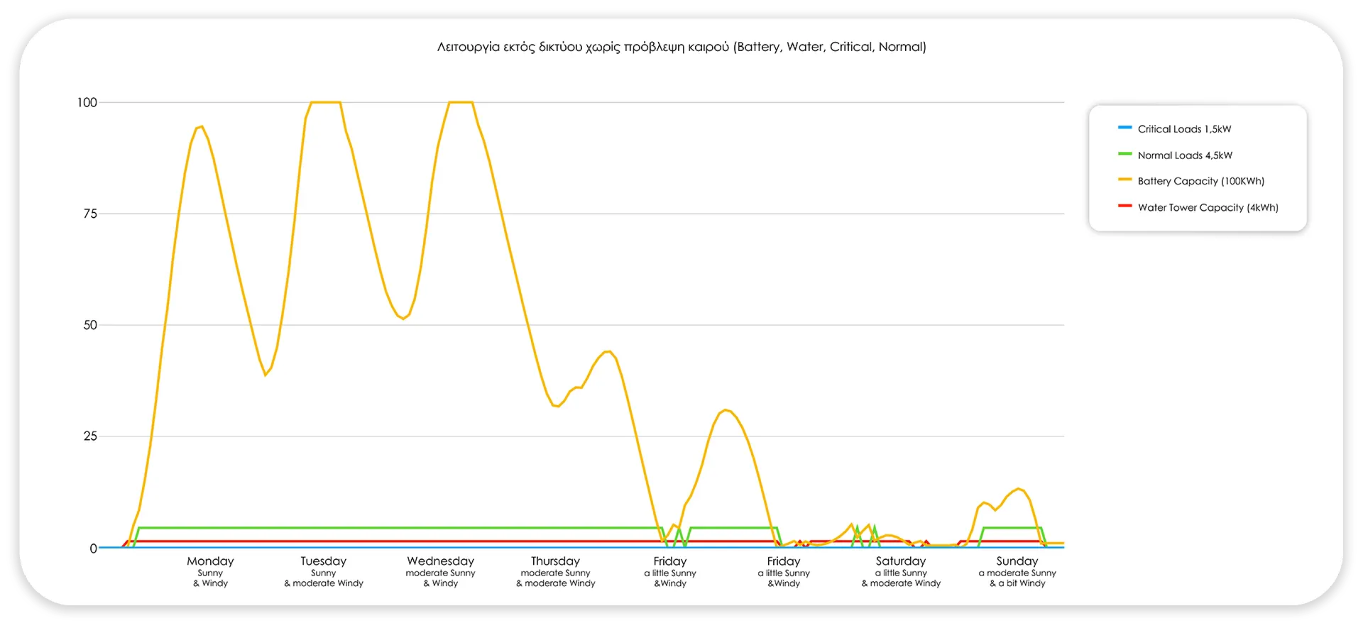
Without weather forecasting and without a water tower the system often fails to keep critical loads on line.
Scenario 2: Off-Grid mode without weather forecast
In this simple setup, the microgrid operates entirely in isolation, without external data inputs such as weather forecasts. The primary goal of the AmEFC controller in this scenario is simply to manage energy production from renewable energy sources (RES) effectively and direct any excess energy directly to the water tower for storage. This scenario represents a basic yet essential test of the system's capabilities for autonomous energy management.
Without weather forecasting the system fails to keep critical loads online, even with the use of energy storage in the hydro tower.
Scenario 3: Off-Grid mode with built-in weather forecast
Based on the previous setup, this script integrates actual real-time weather forecast data into the system. With this addition, the AmEFC controller not only manages energy generation and storage, but also proactively adjusts energy distribution strategies. By anticipating possible power shortages or surpluses, based on weather data, the controller can ensure uninterrupted supply to critical loads. At the same time, it can disconnect, temporarily, the normal loads as a movement strategy to save energy during the periods of low production foreseen.
Weather forecasting protects the system and ensures the safety of critical loads, using energy from the water in the tower for fine-tuning, turning off the rest of the loads when necessary.
Through these successive challenging scenarios, we aim to measure the AmEFC controller's operating efficiency, adaptability, and decision-making ability in various real-world microgrid situations.
Scenario 4: Hybrid operation with network connection
The final and most complex test scenario introduces the possibility of connecting the microgrid to the larger city grid. In this arrangement, AmEFC dynamically manages excess energy by making decisions about whether to store energy in the tower or sell it to the grid. The main objective is to ensure that all loads remain continuously operational by exploiting the benefits of energy storage and energy sales. This scenario shows the potential of the AmEFC controller in a more integrated energy landscape, where microgrids can interact with larger energy infrastructures.
The system, connected to the grid, keeps the critical and normal loads running (100%) with the same priorities, first using the excess storage in the water tower and selling the extra to the PPC.
Financing
The AmEFC (EMION) is funded by the General Secretariat for Research and Innovation of the Hellenic Republic, with proposal number [T2EDK-02878], funded by the European Union.
The project is carried out under the auspices of the Special Service for the Management and Implementation of Actions in the Fields of Research, Technological Development, and Innovation (SSMI). With co-funding from Greece and the European Union.
Research and results for the Autonomous Controller
ΙΩΝΙΚΗ Autonomous
As the installation of Renewable Energy Sources (RES) expands, a critical need arises for the best possible utilization of the produced energy. The answer to how to achieve the production and optimal management of renewable energy lies in these lines. The proposed system includes photovoltaic panels and Vertical Axis Wind Turbines (VAWTs), which produce energy based on sunlight and wind speed. The surplus energy can either be stored in available batteries or converted into potential energy through pumped hydro, lifting water from a lower reservoir to a water tower. This energy can be utilized for electricity generation when demand exceeds production. Regarding the water in the water tower, the conversion of potential energy back into electricity is done via a hydro-generator. In cases where production, combined with energy availability, cannot meet demand, a connection to the HEDNO network has been planned, and for cases of extensive outages in the provider's operation, the installation of a diesel generator has been anticipated.
The standard microgrid has the innovation of centralizing and features the DC Bus as its main energy source. This means that by utilizing the DC Bus, the producer can connect various networks, which can operate independently and/or in parallel. To clarify, three-phase inverters can be connected to drive three-phase loads, while two independent single-phase inverters can be connected to drive two independent single-phase loads. The controller, having predefined the critical loads, can perform calculations for all networks, "thinking" and "deciding" for all at once as if it were a cohesive network.
Naturally, the organization and prioritization of all the aforementioned capabilities of the system is the responsibility of a pioneering autonomous controller (AmEFC), which makes decisions regarding energy utilization. A key factor influencing energy distribution is the categorization of loads. Depending on the criticality of the loads, their priority is determined. The other factor that influences the controller’s decisions is the forecasts it receives regarding sunlight and wind speed for the upcoming days. Furthermore, through this innovative software, access to operational data from all system components is provided, allowing for parameter modifications and reduction of wear and tear on the microgrid.
An overwhelming advantage of the system as a whole is the potential for expansion of each of its segments. Particularly noteworthy is the innovation in the selection of inverters, which is precisely related to the project's objective. This very capability is what paves the way for the implementation of the proposal on a larger scale. The aim is to interconnect such microgrids within the urban fabric and to enhance energy management even further through the collaboration of respective controllers.
Goals
The main objectives on which this study is based as a whole are the following:
- Reliability and durability through dynamic adjustments to electricity production and consumption.
- Optimal energy management with balancing supply and demand through assessment of capacity of energy production and knowledge of weather forecasts.
- Scalability, which is achieved through the ability to adapt the systems to changes in demand, but also the flexibility to integrate new RES. Also particularly important is the possibility of microgrids to operate on a city scale, exchanging resources with other microgrids.
Detailed presentation of microgrid sections
Subsequently, a more detailed presentation will be given regarding the design, theoretical framework, technological advancements, and practical applications of each segment of the microgrid, shedding light on their potential to prevail in the field of renewable energy source integration
1. Basic elements of the microgrid standard
- Solar Photovoltaic (PV) Systems: Based on modularity, they allow the system's scalability and adaptation to changing energy needs
- Vertical AxisWind Turbines (VAWT) Their design ensures low acoustic disturbances, while ground-level accessibility simplifies maintenance tasks. Additionally, these wind turbines demonstrate increased efficiency even under adverse weather conditions, harnessing energy even when conventional wind turbines may face challenges. The design here is also envisioned to be modular, facilitating future expansions as needed.
- Pumps Utilizing the ability of the gravitational potential energy, the pumps offer a reliable and επεκτασιμό medium for storing energy for future use.
2. MPPT charge controllers
Another integral part of the microgrid are the MPPTs, whose role is to track the maximum power point of Renewable Energy Sources (RES). Designed to optimize the utilization of exported energy, each RES is individually connected to its corresponding MPPT.
Also facilitate the exchange of data in real-time through direct configuration of the data in the cloud. The interconnection of these MPPTs is completed in the DC Bus, which operates as a single centre for the distribution and management of energy. The modular approach ensures the scalability.
3. Battery arrays
To enhance the reliability of the microgrid system, battery arrays have been integrated into it. The microgrid offers flexibility in battery technology selection, providing options for either Lead-Acid batteries or advanced Lithium-ion battery systems.
Each battery array is equipped with a state-of-the-art Battery Management System (BMS), which plays a vital role in safeguarding the health and lifespan of the batteries through precise control of their charging and discharging processes.
Just like the MPPTs, Battery Management Systems (BMS) also have the capability to transmit real-time data regarding battery performance and health metrics to the battery manufacturer's cloud platform. This integration of data paves the way for remote monitoring, health diagnosis, and predictive analysis, providing stakeholders with valuable information about battery performance and expected lifespan.
4. Single-phase inverters
If energy consumption requirements expand in the future, the architecture of the microgrid easily allows for scalability without necessitating a complete overhaul of the central infrastructure.
These inverters are not merely passive elements. They are equipped with sensors and communication units that continuously monitor the flow of energy. These data are transformed in real-time into the cloud platform maintained by the inverter manufacturer. The integration with the cloud facilitates remote monitoring, analytical processing, and predictive maintenance, reducing inertia and ensuring continuous energy delivery.
Additionally, the inverters are interconnected, forming an internal communication network. This interconnection among the inverters is crucial for coordinating their operations, maintaining phase consistency, and ensuring a balanced load distribution in the three-phase system.
5. Microgrid loads
Within the complex architecture of the AmEFC microgrid prototype, energy consumption evolves intelligently based on the significance and priority of the connected loads. The following load categories are identified in our system:
Critical Loads: Typically included in these are life support systems, regulated healthcare environments, emergency lighting installations, communication systems, and other essential services. The system operates on the premise that critical loads will never cease their function. | Normal Loads Representing the majority of consumption, they encompass the devices and systems of daily life, from lighting and climate control to household appliances. Although these loads also benefit from uninterrupted electrical power supply, there exists a hierarchy of service. | Hydro Tower Load In cases where energy production significantly exceeds consumption, instead of letting this energy go to waste, the system directs it to the hydro tower. These pumps, after evaluating weather conditions and battery data, convert the surplus electrical energy into potential energy. |
6. Support from HEDNO and auxiliary sources
Network Connectivity: It provides support, especially during extended periods of low renewable energy production or during unforeseen spikes in demand. The system, which draws energy from the grid, ensures that its internal energy balance remains unaffected, while in case of energy surplus, it can be fed back into the grid
Diesel GeneratorThis compensatory energy source can be activated immediately by bridging any gaps in energy, ensuring that the microgrid remains operational and continues to power its loads without interruptions.
7. Grid discharge capabilities
Another critical point is the management of excess production. In systems that include wind turbines, it is very common to exceed the production, not only the demand, but also the capacity of the battery, especially if the associated units battery is saturated. In contrast with the conventional methods of dealing with the excessive supply, such as the disconnection of the wind turbine or the redirection of energy in a resistor, the standard microgrid AmEFC presents an innovative solution. In the case of the water tower, in which is stored the water, reaches the maximum, it has provided a backup plan to redirect the overflow into an adjacent creek. This ensures a constant balance and prevent the waste of energy.
8. AmEFC Software: The processing center of the microgrid
The efficiency of the AmEFC microgrid is not only found in its technical characteristics. At the heart is AmEFC software, an advanced computing and control tool designed to seamlessly harmonize the complex combination of energy flows throughout the system. The main functions of this software are the following:
Equipment Data Flow to the Cloud: Almost every device in the microgrid, not only performs its designated function, but constantly communicates important real-time operation data to the corresponding clouds, thus increasing system performance.
Data Aggregation and Storage: All information is systematically organized and stored, which ensures that every decision the system makes is based on complete, up-to-date information.
Advanced Computational Strategies: Using Optimal Power Flow (OPF) strategies, it determines the most efficient distribution of power in the network, ensuring that each element operates at the peak of its potential while meeting the demands of the connected loads.
Reinforcement Learning (RL)-control: The software learns from historical data, recognizes patterns and adapts to new situations and in this way RL makes its predictive decisions.
Real-time decision-making and automatic control: The combined use of OPF and RL ensures that the software is also proactive. The system continuously makes real-time decisions to maintain optimal energy flow and system efficiency.
9. The backbone of AmEFC execution
The collaboration between software and hardware ensures seamless power flow, ensuring optimal system performance and reliability. More specifically:
Hardware Interface: At the core of the AmEFC controller's functionality is its comprehensive electrical connectivity to a large number of microgrid devices and loads. This is achieved via a relay panel. These relays operate with or without an interface, allowing the controller to organize power distribution by making or breaking connections whenever required.
Client-side software functionsTailored specifically for the specific microgrid requirements, this software continuously retrieves data from the Cloud Center, leveraging it to make timely decisions about power allocation and flow.
Dynamic Power Flow Control: The software can quickly connect or disconnect various components, allowing it to respond immediately to changing energy demands or fluctuations in supply.
10. Challenges of interconnection and opportunities for AmEFC microgrids in urban scaling.
A fundamental challenge lies in synchronizing multiple microgrids with various production capacities, consumption patterns, and operational conditions. The constant expansion of Renewable Energy Sources (RES), which heavily depend on environmental factors, means that in scaling up these microgrids, there can easily be microgrids producing surplus energy while others fall short at that moment
Read more about Autonomous controller microgrid
Results and conclusions
A pivotal point of understanding before analyzing the system's performance is the initialization stage, characterized by zero energy or storage production. This stage serves as the reference point against which we'll assess the system's response to various external environmental influences. The adaptability and efficiency of the AmEFC can be better observed when the system is subjected to a series of weather conditions. To differentiate this, we classify climatic conditions based on two primary factors: solar radiation and wind speed. These factors are further divided into three discrete categories for detailed analysis.
The differentiation of the categories is based on
Solar Radiation
- Day with high sunshine
- Day with moderate sunshine
- Day with little sunshine
Wind Speed
- Day with high wind speed
- Day with moderate wind speed
- Day with low wind speed
The following sections will examine the detailed interaction between these climatic conditions and the corresponding energy production, revealing the resilience and reliability of the AmEFC microgrid system.
Sunshine (w/m2 high) | Wind (m/2 high) | Moderately sunny (w/m2 ) | Moderately windy(m/2 ) | A little sunny(w/m2 ) | A bit windy (m/2 ) |
---|---|---|---|---|---|
0 | 4.1 | 0 | 3.8 | 0 | 0.3 |
0 | 5.2 | 0 | 4.0 | 0 | 0.4 |
0 | 6.5 | 0 | 4.3 | 0 | 0.5 |
0 | 7.3 | 0 | 4.5 | 0 | 0.7 |
100 | 8.0 | 10 | 4.7 | 10 | 0.8 |
400 | 8.5 | 50 | 5.0 | 30 | 0.9 |
600 | 9.0 | 150 | 4.8 | 50 | 1.0 |
800 | 9.3 | 300 | 4.6 | 70 | 1.1 |
900 | 9.5 | 400 | 4.5 | 90 | 1.2 |
1000 | 9.8 | 450 | 4.7 | 100 | 1.3 |
1100 | 9.4 | 350 | 5.1 | 110 | 1.0 |
1000 | 8.7 | 300 | 4.9 | 120 | 0.8 |
1100 | 7.8 | 450 | 4.6 | 130 | 0.6 |
1000 | 7.2 | 500 | 4.4 | 120 | 0.5 |
900 | 6.6 | 450 | 4.2 | 110 | 0.4 |
Weekly simulation of the AmEFC microgrid
To rigorously test the AmEFC microdistribution system and, more importantly, the controller's operational performance, a full week-long simulation was set up. The simulation was structured to cover a variety of climate conditions by combining the aforementioned categories of solar radiation and wind speed. The sequence provides a comprehensive picture, covering both optimal and worst-case conditions to assess system adaptability, resilience and efficiency.
Below is the sequence for the week:
Days | Sunshine | Category | Wind speed | Category |
---|---|---|---|---|
Day 1 | High Sunshine | A | High | A |
Day 2 | High Sunshine | A | Moderate | S |
Day 3 | Moderate Sunshine | S | High | A |
Day 4 | Moderate Sunshine | S | Moderate | S |
Day 5 | Low Sunshine | C | High | A |
Day 6 | Low Sunshine | C | Moderate | S |
Day 7 | Moderate Sunshine | B | Low | C |
This sequence, which includes a combination of solar radiation and wind speed, forms the core of the simulation. The data generated from this combination of conditions enables AmEFC to adapt and optimize energy flow, thus underscoring its real-world practicality and robustness.
A series of graphs are presented that depict the mutual impact between the primary environmental factors - solar radiation and wind speed - and energy production in the system. These visualizations stem from week-long observations where days were categorized based on the prevailing weather conditions (sunshine and wind). This categorization not only simulates the system's response under various real conditions but also emphasizes the flexibility and efficiency of the AmEFC controller. Each graph is designed to provide a detailed picture of daily trends, peaks, troughs, and anomalies, offering an overall understanding of how the system adapts to various energy input scenarios for optimal energy distribution during different simulations
Test scripts for the AmEFC controller
To confirm the efficiency and adaptability of the AmEFC controller in a variety of environments, we have designed four different scenarios. Each of these scenarios introduces incrementally added complexities and functions, simulating both typical and adverse conditions for the microgrid system:
Scenario 1: Off-Grid operation without weather forecast and without a water tower
In this simple and "bare" setup, the microgrid operates in complete isolation, with no external data inputs such as weather forecasts and no water tower. The main objective of the AmEFC controller in this scenario is simply to efficiently manage the power generation from the RES. This scenario represents a basic, but also essential, check of the system's capabilities for autonomous energy management.
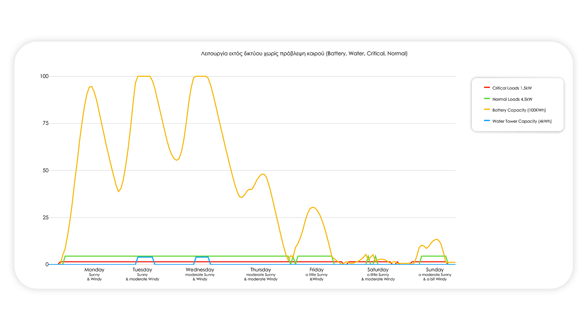
Without weather forecasting and without a water tower the system often fails to keep critical loads on line.
Scenario 2: Off-Grid mode without weather forecast
In this simple setup, the microgrid operates entirely in isolation, without external data inputs such as weather forecasts. The primary goal of the AmEFC controller in this scenario is simply to manage energy production from renewable energy sources (RES) effectively and direct any excess energy directly to the water tower for storage. This scenario represents a basic yet essential test of the system's capabilities for autonomous energy management.
Without weather forecasting the system fails to keep critical loads online, even with the use of energy storage in the hydro tower.
Scenario 3: Off-Grid mode with built-in weather forecast
Based on the previous setup, this script integrates actual real-time weather forecast data into the system. With this addition, the AmEFC controller not only manages energy generation and storage, but also proactively adjusts energy distribution strategies. By anticipating possible power shortages or surpluses, based on weather data, the controller can ensure uninterrupted supply to critical loads. At the same time, it can disconnect, temporarily, the normal loads as a movement strategy to save energy during the periods of low production foreseen.
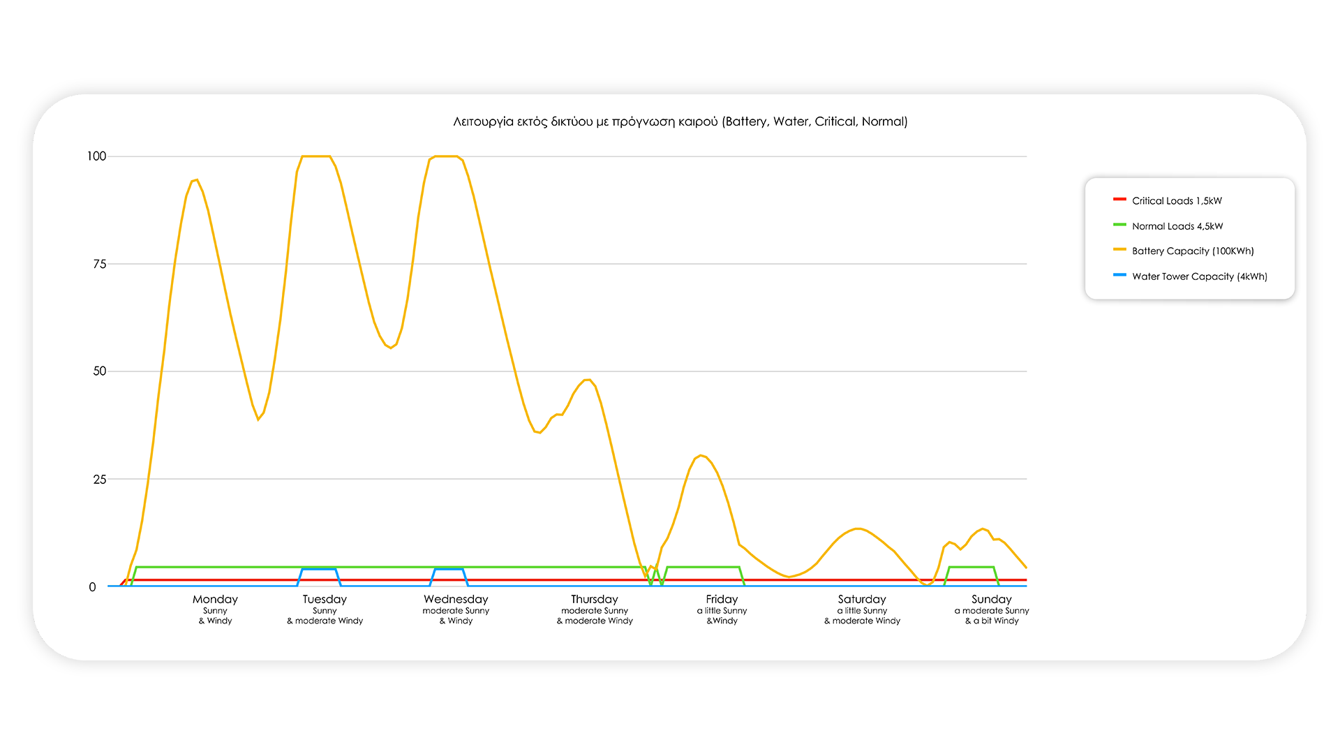
Weather forecasting protects the system and ensures the safety of critical loads, using energy from the water in the tower for fine-tuning, turning off the rest of the loads when necessary.
Through these successive challenging scenarios, we aim to measure the AmEFC controller's operating efficiency, adaptability, and decision-making ability in various real-world microgrid situations.
Scenario 4: Hybrid operation with network connection
The final and most complex test scenario introduces the possibility of connecting the microgrid to the larger city grid. In this arrangement, AmEFC dynamically manages excess energy by making decisions about whether to store energy in the tower or sell it to the grid. The main objective is to ensure that all loads remain continuously operational by exploiting the benefits of energy storage and energy sales. This scenario shows the potential of the AmEFC controller in a more integrated energy landscape, where microgrids can interact with larger energy infrastructures.
The system, connected to the grid, keeps the critical and normal loads running (100%) with the same priorities, first using the excess storage in the water tower and selling the extra to the PPC.
Financing
The AmEFC (EMION) is funded by the General Secretariat for Research and Innovation of the Hellenic Republic, with proposal number [T2EDK-02878], funded by the European Union.
The project is carried out under the auspices of the Special Service for the Management and Implementation of Actions in the Fields of Research, Technological Development, and Innovation (SSMI). With co-funding from Greece and the European Union.