
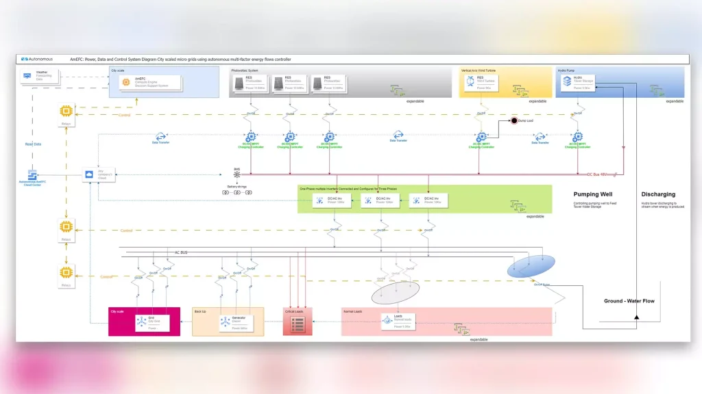


The Autonomous Energy Flow Controller is a product that has the ability to optimally manage energy produced by Renewable Sources, based on weather forecasts. More specifically, the controller receives through the cloud data concerning the energy produced by the microgrid that it controls, weather estimates for the next 5-7 days and based on these it makes its decisions.
In cases where the production exceeds the demand, then it makes decisions regarding the storage of energy or the supply of loads beyond the critical ones, while in cases where it lags behind the demand, then it gives specific orders, so that the requirements of the loads are met. The controller consists of a box, inside which a Raspberry Pi board is installed and the front of which is a Pi screen, through which the user operates the invention.
The controller uses a specific decision-making algorithm, and is connected via relays to the central electrical panel of the microgrid, so that based on these decisions, it can make the required modifications to the producers and/or consumers of the microgrid.
Specifications
The Autonomous Controller has a Pi Display 7” LCD touch screen, resolution 1024×600. Features 8GB RAM, 64-bit quad-core processor, support for dual displays up to 4K resolution via a pair (2) micro-HDMI ports, 1 Gigabit Ethernet port, 4 USB ports (2 USB 2.0 & 2 USB 3.0), wireless LAN , Bluetooth 5.0, 1 stereo 4-pole audio output and USB-C power supply. The main board of the Autonomous Controller is a Raspberry Pi 4 – Model B.
Connectivity of Autonomous Flow Energy Controller
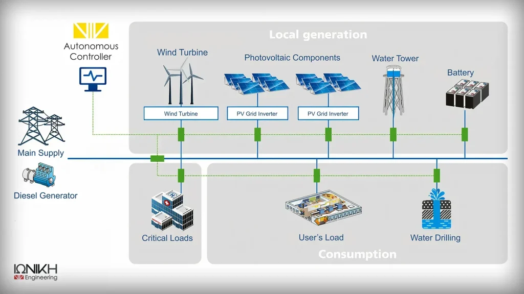
As already mentioned, the Autonomous Controller receives operating data from the inverters of each installation and weather forecasts for the next 5-7 days and based on these, makes decisions about the operation of its loads.
The Autonomous Controller connects either wired or wirelessly to the network and has the ability to receive data from any inverter via the cloud. This is achieved because all companies that produce inverters use specific encoding protocols for the data they send and the user can download via open APIs & JSON Queries. Based on this data, the controller decides whether or not to supply specific loads, whether or not to connect to the grid and any other action.
The controller implements the decisions through 8 outputs that it has and which end up in the installation's electrical panel. This means that it is possible to control 8 different lines of each table. In fact, the user has two options for placing the controller. It can either be placed on the door of the installation's electrical panel, or near it.
To complete the installation - interfacing the controller with the panel, a relay expansion board is required, which is inserted between the controller and the electrical panel. Constructionally, this board has a form such that it can apply the sockets of the electrical panels.
Read more about inovate microgrid in which the Autonomous Power Flow Controller is applied.
Software
The Autonomous Flow Energy Controller uses Linux software. Users can connect through a browser to the CITIBILL application and specifically to e-energy, where the data that the controller receives from Renewable Sources are gathered. Production statistics from photovoltaics and wind turbines are presented. At the same time, the controller receives the weather forecasts for the following days. Controller decisions can be programmed by the administrator and decisions made automatically, without requiring intervention
The controller screen is divided into 6 windows. The windows at the top of the screen show the power generation subsystems (subsystem of small wind turbines, photovoltaics and hydro generators) with power in kW and energy production in kWh.the lower part of the screen shows the subsystem of the loads with power indicators in kW (indicatively, critical loads are displayed, usually the water lifting pump), the current calendar moment and includes the ideal emergency button (emergency button) which can be deactivated by touching it the entire microgrid by stopping power flows to all relays controlled by the controller. Also displayed is the settings subsystem which includes virtual keys for monitoring power flows, settings and turning off the controller display.
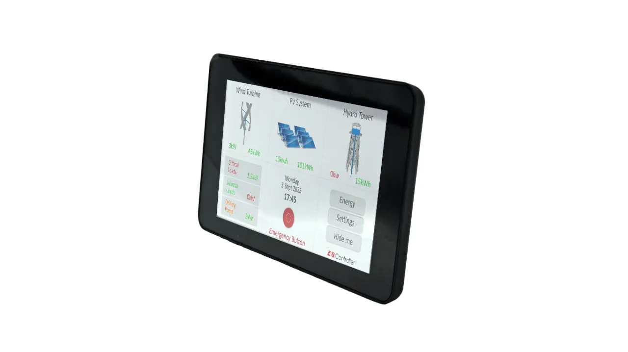
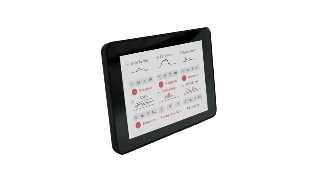
In case the user touches the "Energy" button on the first screen of the figure, he is transferred to the environment of the adjacent figure. Here are presented production data from APE, loads, weather data and DEDDIE data. The user can modify the time period of the data through 4 touch keys that appear on his screen and concern daily, monthly, yearly and total data. Emergency shutdown keys are also displayed on this controller screen interface.
Remote operation
The user has the ability to enter the system from any device with network access, monitor the data collected by the controller, check the system for possible faults and of course make modifications to the system settings. The system automatically updates and modifies its commands through the respective relays.
Scalability
Of particular interest are the prospects for expanding the operation of the Autonomous Controller. More specifically, by using data from his previous decisions, the controller can optimize his future decisions, reducing failures and minimizing the risk of failure to predict weather forecasts.
Financing
The AmEFC (EMION) is funded by the General Secretariat for Research and Innovation of the Hellenic Republic, with proposal number [T2ΕΔΚ-02878], financed by the European Union.
The project is run under the auspices of the Special Service Management and Implementation of Actions in the Areas of Research, Technological Development and Innovation (EYDE RTDI). With the co-financing of Greece and the European Union.
Σχεδιασμός
Αδειοδότηση
Χρηματοδοτήσεις
Υποστήριξη
Construction
Energy
Environment
Υγεία & Ασφάλεια
Cloud
Σχεδιασμός
Αδειοδότηση
Χρηματοδοτήσεις
Υποστήριξη
Construction
Energy
Environment
Υγεία & Ασφάλεια
Cloud