Autonomous energy flow controller, the general overview of which has already been conducted in previous articleIt concerns the optimal management of energy generated from Renewable Sources, aiming to maximize the system's efficiency. More specifically, the controller is part of a microgrid, where energy production and consumption coexist, and its algorithm, utilizing weather data, determines the utilization of the aforementioned energy.
The structural components of the system, which operate either as electricity producers or consumers with their respective electrical characteristics, are presented in detail. Furthermore, the hardware device to be developed for managing all this data is outlined. Lastly, the controller selected for the system's development is introduced, along with its corresponding features.
Electricity Producers and Consumers
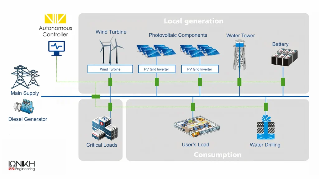
The hybrid system to be developed consists of the following parts
- Photovoltaic panels with a total power of 41.04 kW
- Photovoltaic panels with a total power of 41.04 kW
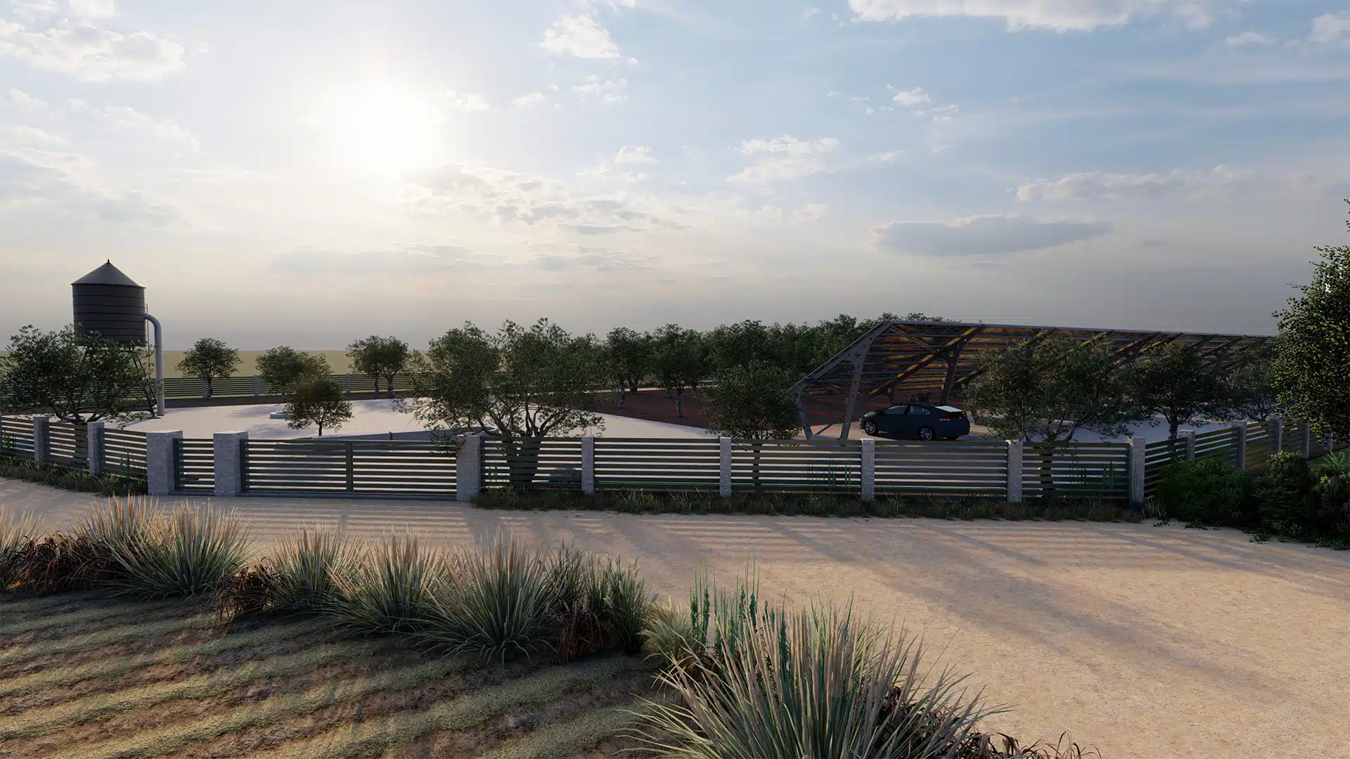
- Water tower with a 2.00 kW hydro generator
- Lead-acid energy storage accumulators (RES OPzS), with a total capacity of 220.00 kWh
- Electricity Distribution Network
- Installation consumption loads with a total power of 10.00kW
Some of these elements operate as producers of electrical energy, while others function as consumers.
More specifically, electricity generation arises from the following:
α)Solar panels
b. Wind turbine
c)Water Tower System with Hydro Generator
d)Electricity Distribution Network Operator
e)Accumulators (during discharge phase)
Electrical energy is consumed by the following elements.
a. Installation loads
b. Accumulators (during the charging phase)
c. Drilling (during the filling phase of the water tower)
Next, a detailed presentation will be provided of all parts of the system along with their technical and electrical characteristics
Photovoltaic panels
Photovoltaic panels function as an electricity generator. The photovoltaic system to be installed will have a total power output of 41.04 kW and will consist of 72 panels, each with a power of 570 Wp. The panels used will be single-sided, monocrystalline, made of silicon, with 72 cells.
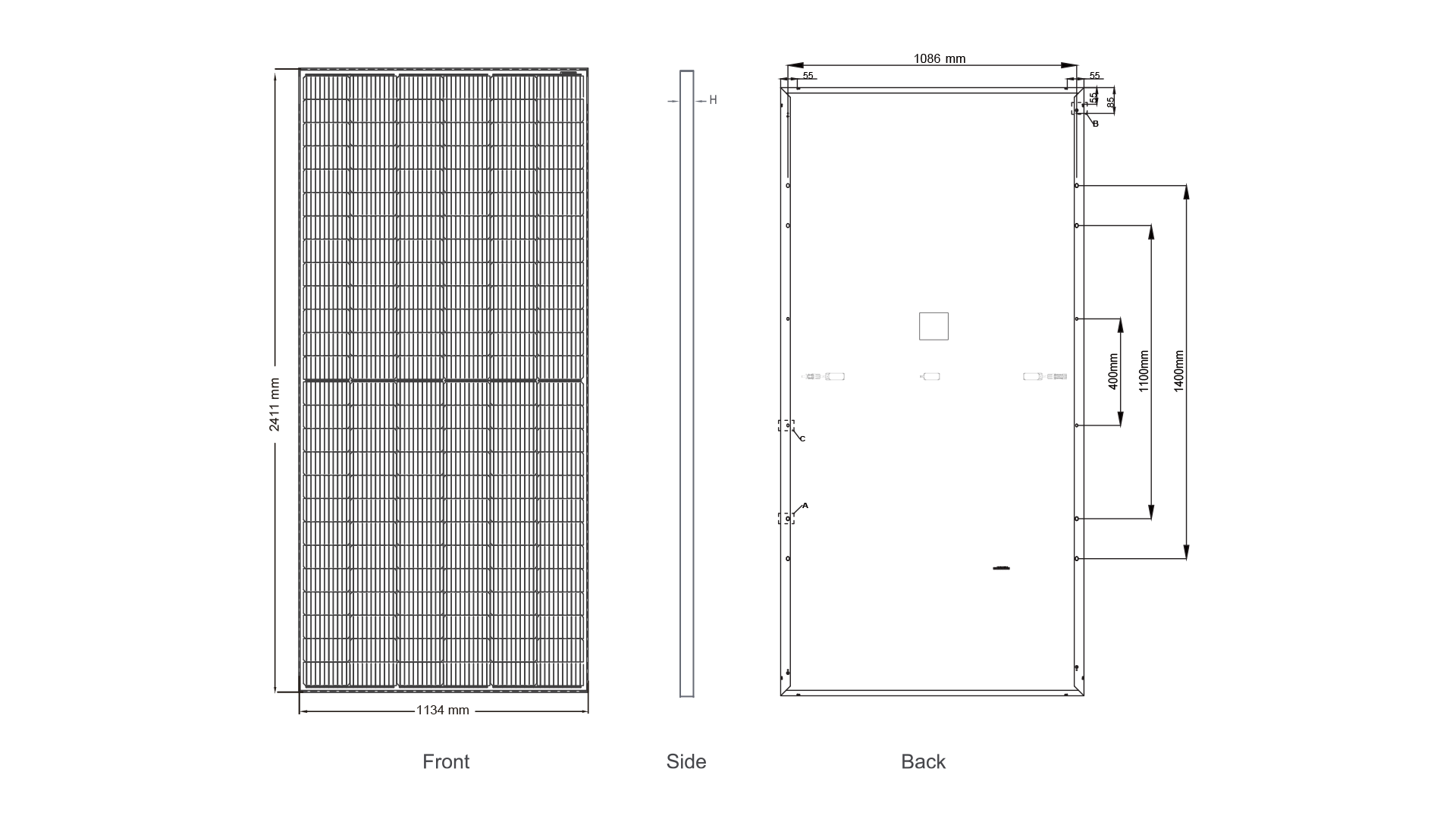
The photovoltaic panels generate electrical energy by absorbing solar radiation. Essentially, it involves converting solar energy into electricity. The current produced by the photovoltaic panels is direct current (DC), while the nominal open-circuit voltage for one panel is 50.11V
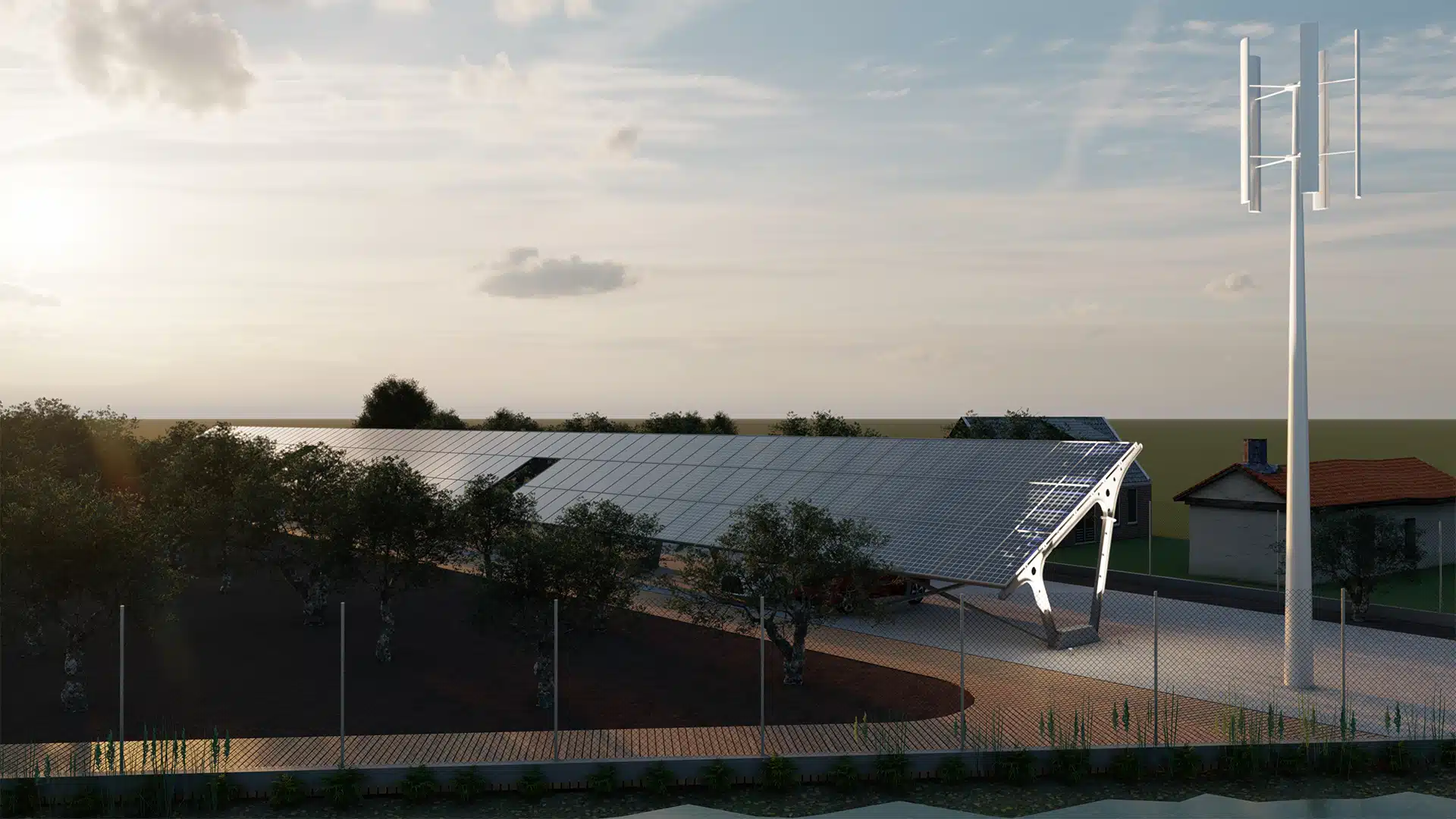
The photovoltaic system will be installed on the ground, and the panels will be placed on fixed metallic support structures
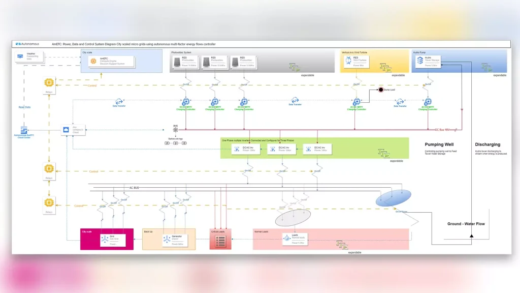
The output of all charging controllers will be connected to a 48V DC BUS arrangement. This arrangement serves as a junction point for connecting the outputs of the charging controllers as well as the entry point to the accumulators. The DC BUS arrangement is responsible for coordinating the charging of the accumulators, enabling maximum efficiency and utilization of the energy generated by the photovoltaic systemsDC BUS 48Vwhich will be installed.
Wind turbine
The wind turbine functions as an electrical energy generator. The wind turbine to be installed will be vertical-axis, with a power of 5.00kW and will be positioned on a 12.00m high metal support pole.
The current generated by the wind turbine is alternating current (AC) with a voltage of 220V. At the output of the wind turbine, a charge controller will be connected with an output voltage of 48V and an output current of 105A. The charge controller will manage the charging process of the accumulators and will halt it when their full charge is detected. Simultaneously, it will allow the automatic restart of the accumulator charging process when it is noticed that their voltage has fallen below a specific charging level. Additionally, the charge controller will monitor the diversion of surplus energy from the wind turbine to the dump load. The output of this charge controller will also be connected to the 48V DC BUS that will be installed.
Hydro generator
The hydro generator functions as an electrical energy producer. A system will be installed consisting of a water tower and a 2.00kW hydro generator. The same system will be connected to a 4.50kW geothermal drill, which will be activated based on the energy requirements of the system being developed. The current generated by the hydro generator is alternating current (AC), with voltages of 38V, 75V, 150V, or 200V (depending on the model).
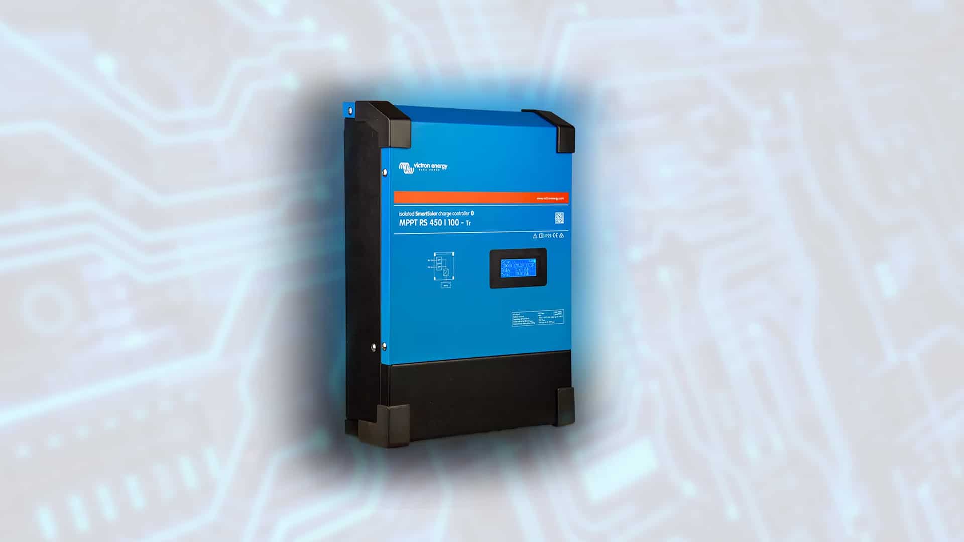
At the output of the hydro generator, a charge controller 48|105 with an output voltage of 48V and an output current of 105A will be connected.
The charge controller will monitor the battery charging process and will interrupt it once their full charge is detected.
The charge controller will monitor the battery charging process and will interrupt it once their full charge is detected. The output of this charge controller will also be connected to the 48V DC BUS that will be installed Below are the connection diagram of the hydrogen generator circuits and the technical and electrical characteristics of the charging regulator that will be installed
At the output of the hydro generator, a charge controller 48|105 with an output voltage of 48V and output current of 105A will be connected. The charge controller will monitor the battery charging process and will interrupt it once their full charge is detected. Simultaneously, it will allow the automatic restart of the battery charging process when their voltage drops below a specific charging level. The output of this charge controller will be connected to the installed 48V DC BUS. Below are the connection diagram of the hydro generator circuits and the technical and electrical specifications of the charge controller that will be installed.
Energy Storage Batteries
Energy storage batteries operate as an electrical energy generator during the discharge phase and as an electrical energy consumer during the charging phase.
In both cases, the current of the batteries will be direct current (DC), at a voltage of 48V.
In this specific application, the installation of batteries with a storage capacity of 220 kWh is required. Two parallel arrays of lead-acid RES OPzS batteries will be used
Each array will consist of 24 batteries with a voltage of 2V and a capacity of 2286AH.
The battery banks will be connected to the central BUS (DC BUS 48V).
Electricity Distribution Network
The battery arrays will be connected to the central bus. producer electric power. The mains current is three-phase, alternating (AC), voltage 400V and frequency 50Hz.
The DEDDIE network will be connected to an arrangement BUS AC, as described below.
Loads of consumption
The loads of the installation function as consumers the total power of the consumption loads is equal to 10,00kWThe loads are categorized into the following three categories.
- Critical loads 1,50kWThese are loads that require continuous and uninterrupted power supply (PCs, lighting, power supplies)
- Normal loads 4,00kWThese are the remaining loads of the installation (PCs)
- Geothermal load 4,50kW: This refers to the drilling that will be connected to the hydropower tower-hydrogenerator system and will be operational according to the system's energy requirements.
The following table shows all the elements of the system to be designed with their corresponding electrical characteristics.
Loads of consumption
| Load | Power (kW) | Type (3Φ/1Φ) |
|---|---|---|
| Critical Loads | ||
| PC 1 | 0.25 | 1Φ |
| PC 2 | 0.25 | 1Φ |
| PC 3 | 0.25 | 1Φ |
| Lighting | 0.3 | 1Φ |
| Transformers | 0.45 | 1Φ |
| Partial Total | 1.5 | 1Φ |
| Normal Loads | ||
| PC 1 | 0.45 | 1Φ |
| PC 2 | 0.45 | 1Φ |
| PC 3 | 0.45 | 1Φ |
| PC 4 | 0.45 | 1Φ |
| PC 5 | 0.45 | 1Φ |
| PC 6 | 0.45 | 1Φ |
| PC 7 | 0.45 | 1Φ |
| PC 8 | 0.45 | 1Φ |
| PC 9 | 0.4 | 1Φ |
| Partial Total | 4 | 1Φ |
| Drilling Load | ||
| Drilling | 4.5 | 3Φ |
| Partial Total | 4.5 | 3Φ |
| Total | 10 | 3Φ |
System electrical characteristics
| System elements | Type (AC/DC) | Output voltage (V) | Total power (kW) | Capacity (kWh) |
|---|---|---|---|---|
| Producers | ||||
| Photovoltaic panels | DC | 50.11 | 7.4 | – |
| Wind turbine | AC | 220 | 5 | – |
| Hydro generator | AC | 38,00V 75,00V 150,00V ή 200,00V | 2 | |
| Accumulators | DC | 48 | – | 220 |
| Electricity Distribution Network | AC | 400 | – | – |
| Consumers | ||||
| Accumulators | DC | 48 | – | 220 |
| Installation loads | AC | 400 | 10 | – |
The consumer loads will be connected to the same arrangement BUS AC to which the DEDDIE network will also be connected.
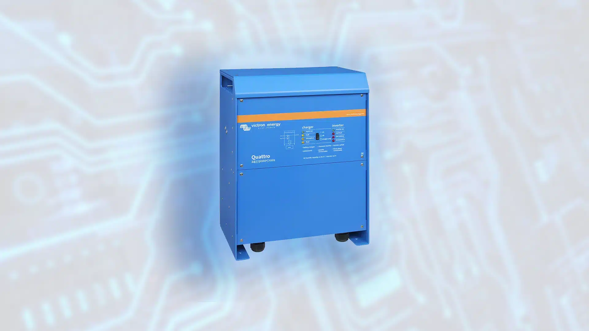
Between the two BUS (AC BUS, DC BUS 48V) three single phase power inverters/chargers will be connected 15,00KW each one. The inverters will convert the DC current into AC in order to supply the loads of the installation while at the same time they will be used to charge the accumulators in cases where this is deemed necessary by the central controller of the system. The output of the inverters will be connected to AC BUS Install the device to provide the load of the device. The following describes the technical and electrical characteristics of the installed inverter, as well as the connection diagram of all the circuits related to the network and the installed load
It is noted that the system to be developed is expandable and any additional devices can be connected such as H/Z, hydrogen generator, wind generator, photovoltaic etc.
ControllerSystem
The system controller for managing microgrids is a Raspberry Pi 4 Model B, which is the latest product in the Raspberry Pi series of computers. It's a complete computer system on a board consisting of a central processing unit (CPU), integrated graphics processing unit (GPU), storage space, RAM, and input/output ports (GPIO).
Specifically, the Raspberry Pi 4 Model B features a quad-core ARM Cortex-A72 64-bit processor clocked at 1.5 GHz. The RAM is LPDDR4 type with a capacity of 4 GB, enabling the execution of complex and parallel processes. Power is supplied through USB-C at 5V and 3A. Furthermore, connectivity can be either wired via Ethernet or wireless through Wi-Fi. Additionally, there's the capability of data transfer via Bluetooth 5.0.
Regarding the use of the controller in the system, the Raspberry Pi will be connected through the relays of the board to the relays of the electrical panel of the installation, thus providing commands to manage the energy flows.
Control system
The purpose of the research project is the design and development of a device (hardware) which will provide the ability to manage and distribute all energy flows resulting from the above producers and consumers. The device will receive the following data as input:
- Climatic data με πρόβλεψη 4-5 ημερών (ηλιοφάνεια, ταχύτητα ανέμου κλπ.)
- consumption Critical load
- consumption Normal load
Depending on the data received, the device will be capable of controlling all connected elements and managing energy distribution to achieve maximum efficiency. For instance, during a sunny day, if a household's photovoltaic panels generate energy and the accumulators are not fully charged, the device will make a decision. If the weather forecast indicates cloudiness the next day, it will charge the accumulators to maintain an adequate energy reserve. Conversely, if it is predicted to be sunny, the device will redirect surplus energy to the grid.
All input data will be fed into software on a computer that will instantly receive data from the device's circuits and determine the corresponding directions of energy flow. To achieve this, a Raspberry Pi Model B controller from the Raspberry Pi series of computers will be developed. Essentially, the controller will receive specific commands to open or close switch contacts (relays), controlling the distribution of energy to and from all elements of the system (solar panels, wind turbine, hydrogenerator, accumulators, the DEDDIE network, consumption loads, and any other device that could be connected).
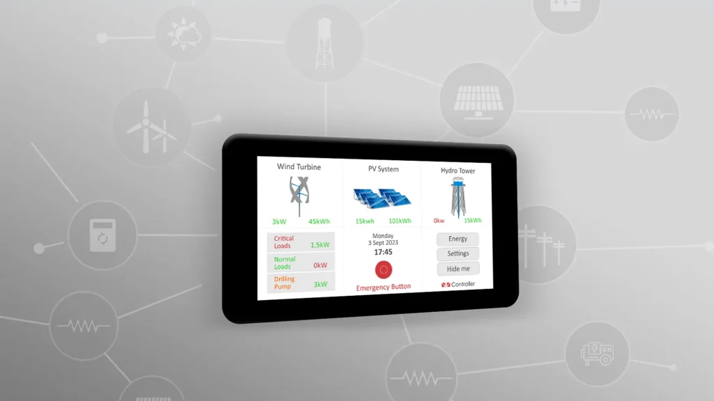
The relays on the board will be powered by a 12V, 3A, 36W power supply. Additionally, a 7-inch touchscreen with a resolution of 1024×600 will be added to the above scheme. It will be connected to the Raspberry Pi using an HDMI cable, and its power will be supplied via a USB cable. Below, the power supply to be used (left) is shown, along with the screen to be connected to the Raspberry Pi (right)
As for the controller's operation to control the system's relays, the procedure followed is as follows:
- Connecting the system's relays to those on the board.
- Developing software running on the Raspberry Pi.
- In the software, reading data from the cloud.
- Depending on the data values and program logic (code), changing the state of the relays on the board to Normal Close or Normal Open for further driving (powering) the relays of the system
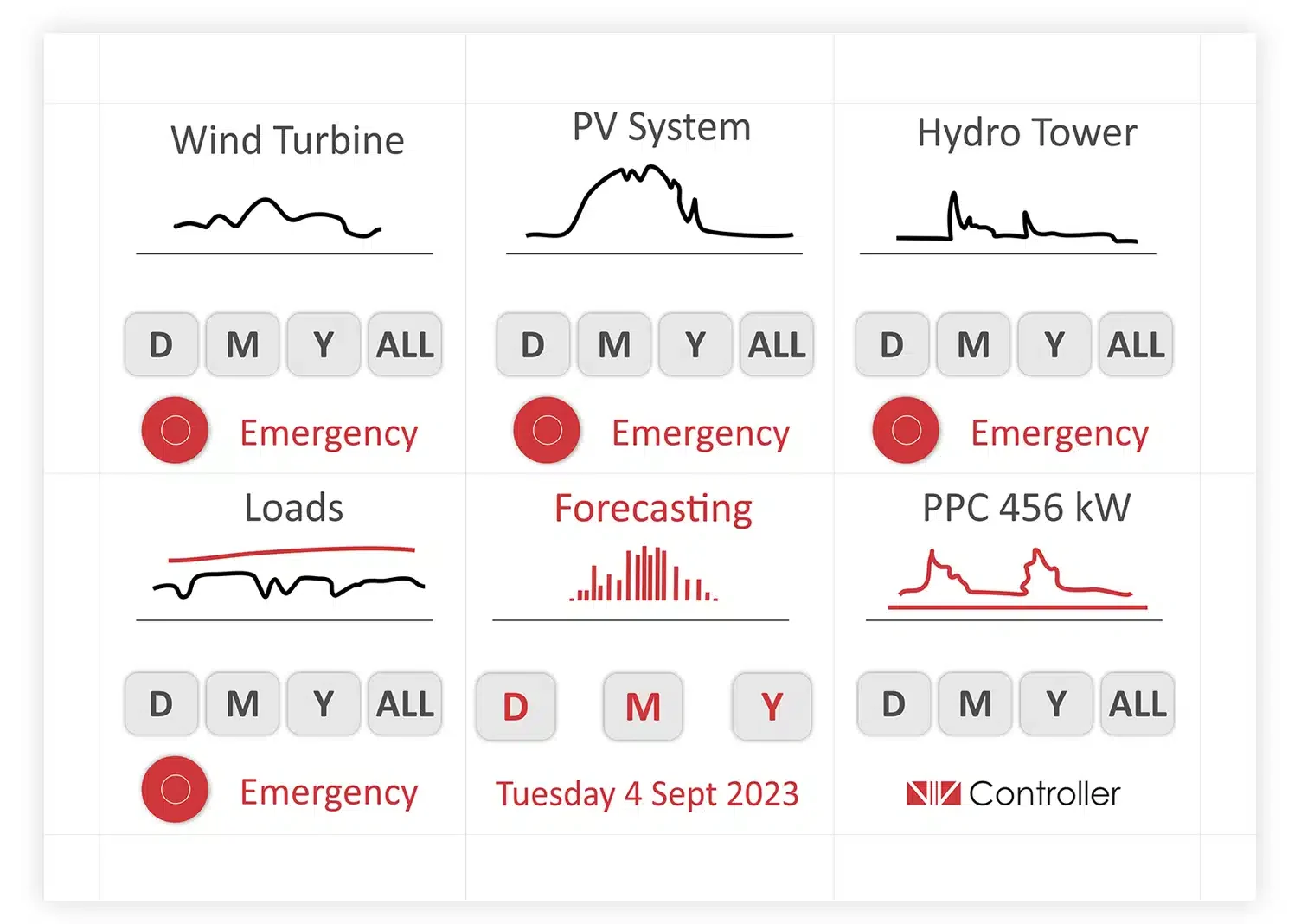
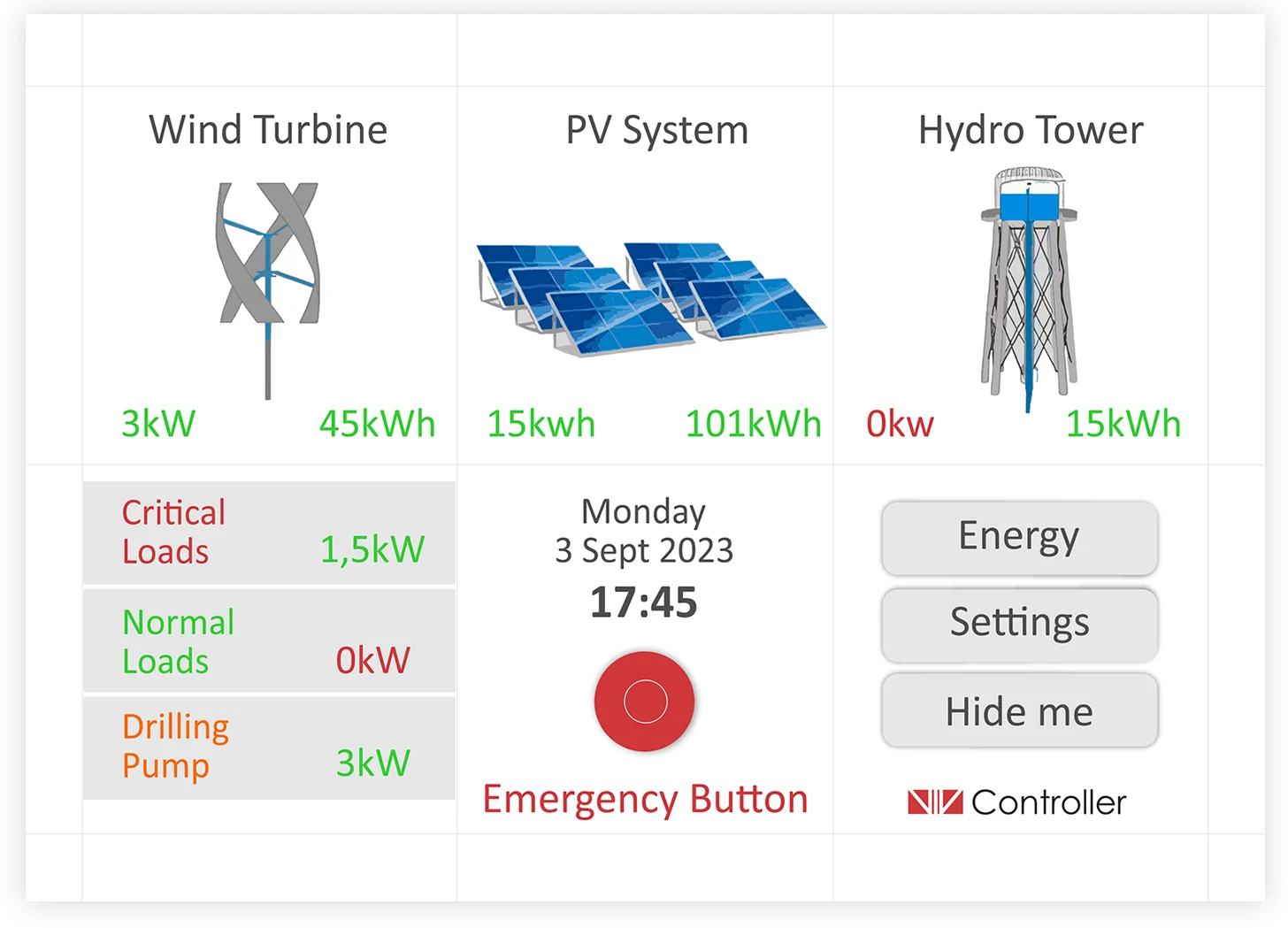
- Display of data on the screen connected to the Raspberry Pi and the ability for further control, such as disabling the entire microgrid and monitoring various energy flows.
On the screen of the controller in which there is all the information about the system being controlled. Observing the images in the figure, it can be concluded that the application responsible for displaying the data consists of three main menus. A common feature of all three is that the screen is divided into six smaller windows.
Finally, it's worth noting that the type of application developed for system control and data display on the screen can be a web, desktop, or mobile application..
In more detail, the control and decision-making system is presented in the article"Autonomous Flow Energy Controller: Hardware“
Financing
The AmEFC (EMION) is funded by the General Secretariat for Research and Innovation of the Hellenic Republic, with proposal number [T2ΕΔΚ-02878], financed by the European Union.
The project is run under the auspices of the Special Service Management and Implementation of Actions in the Areas of Research, Technological Development and Innovation (EYDE RTDI). With the co-financing of Greece and the European Union.